Step 1 - Frame Kit Contents
Apex Base Frame Kit
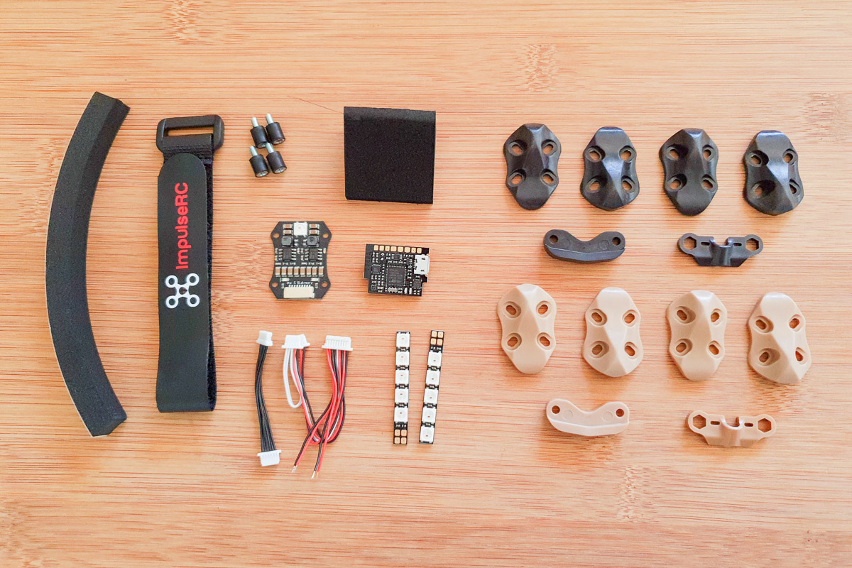
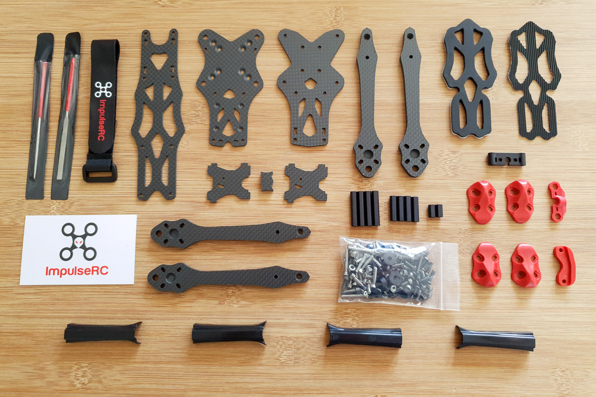
The Apex Base kit includes the following items:
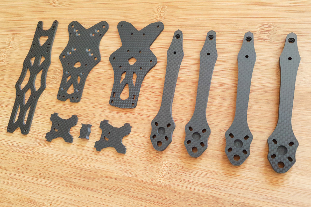
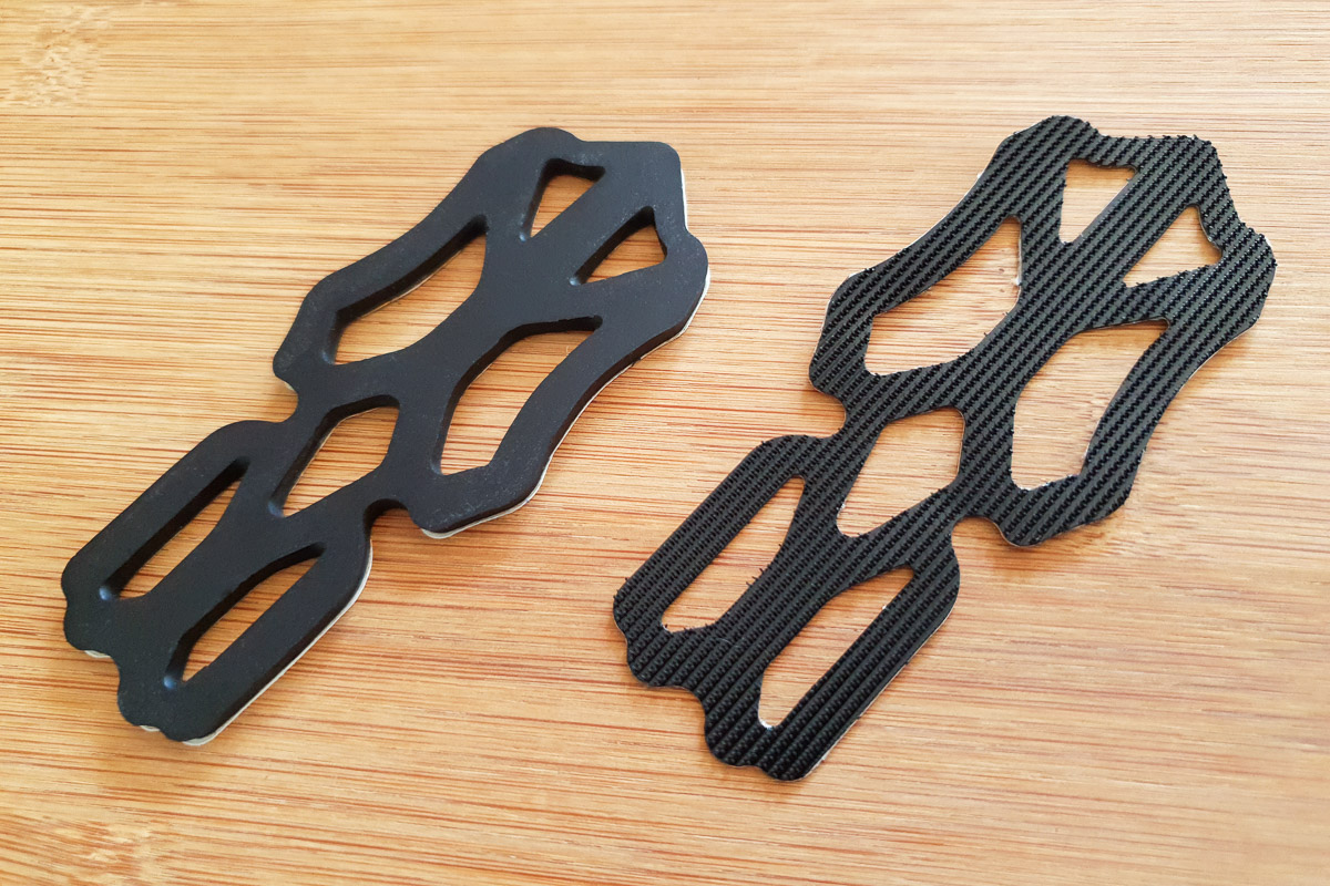
Carbon fiber parts
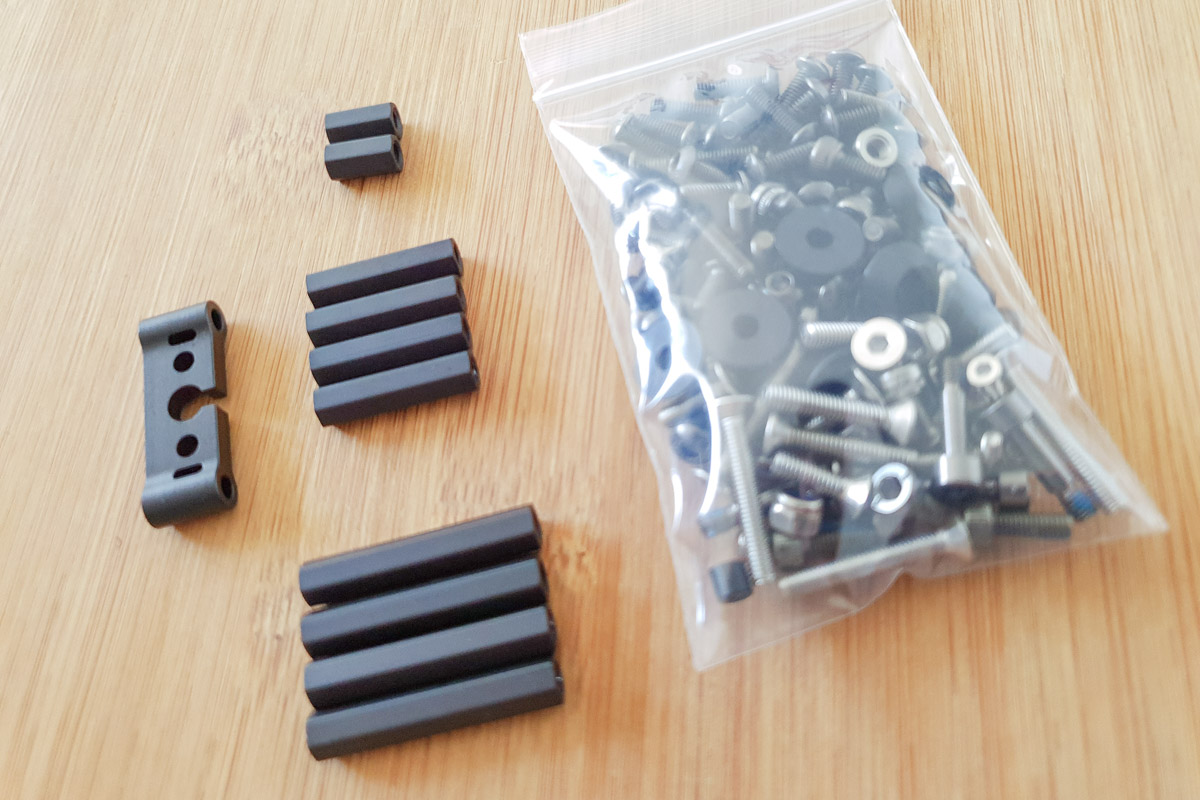
Full hardware kit
Aluminium standoffs and SMA clamp
Rubber battery pad and velcro battery pad
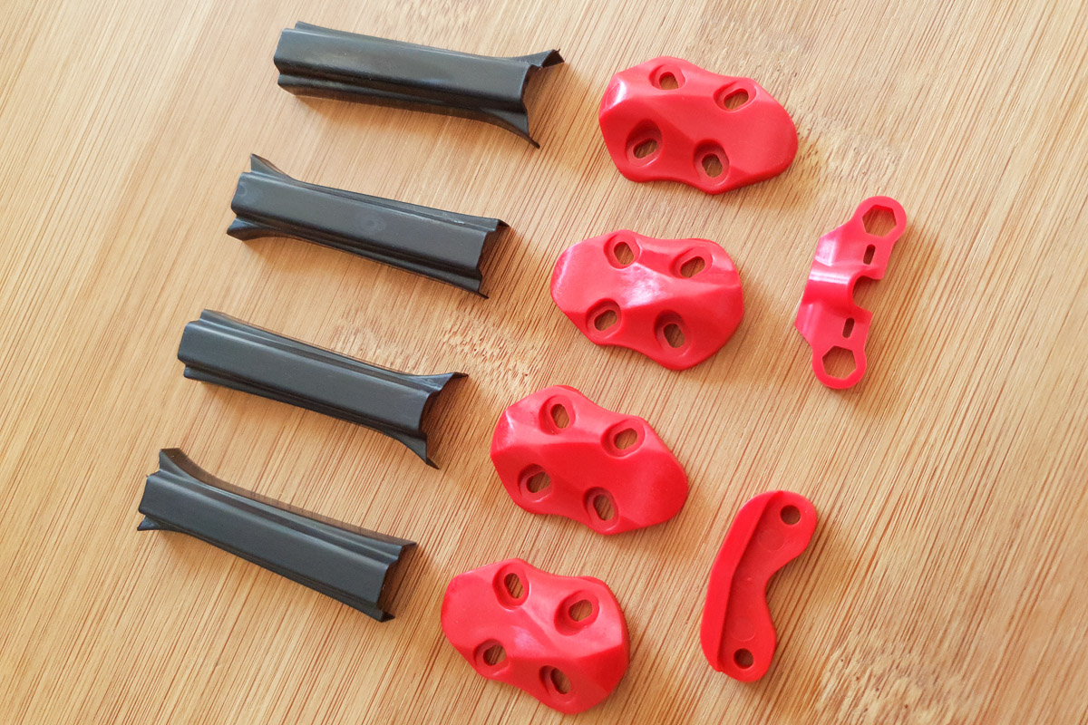
Injection molded skids, bumper and Immortal-T mount
Injection molded motor wire protection
ImpulseRC battery strap
Round and flat diamond files
Warranty card
Apex HD Frame Kit
The Apex HD kit contains the same items as the Base kit with the following minor changes:
The top, upper main and camera plates are modified to fit the DJI air unit and camera
The aluminium SMA clamp is removed because it is no longer required
TPU camera shims are included to adapt the DJI camera to the correct width
Mr Steele Apex Frame Kit
The Mr Steele Apex kit contains the same items as the Base kit, along with multiple extras including custom electronics and wiring harness.
See the Steele Apex section of this page for more details.
Mr Steele Apex Frame Kit - Light Weight
The Mr Steele Apex Light Weight kit contains the same items as the Mr Steele kit, along with upgraded 7075-T6 aluminium hardware to save weight.
See the Steele Apex section of this page for more details.

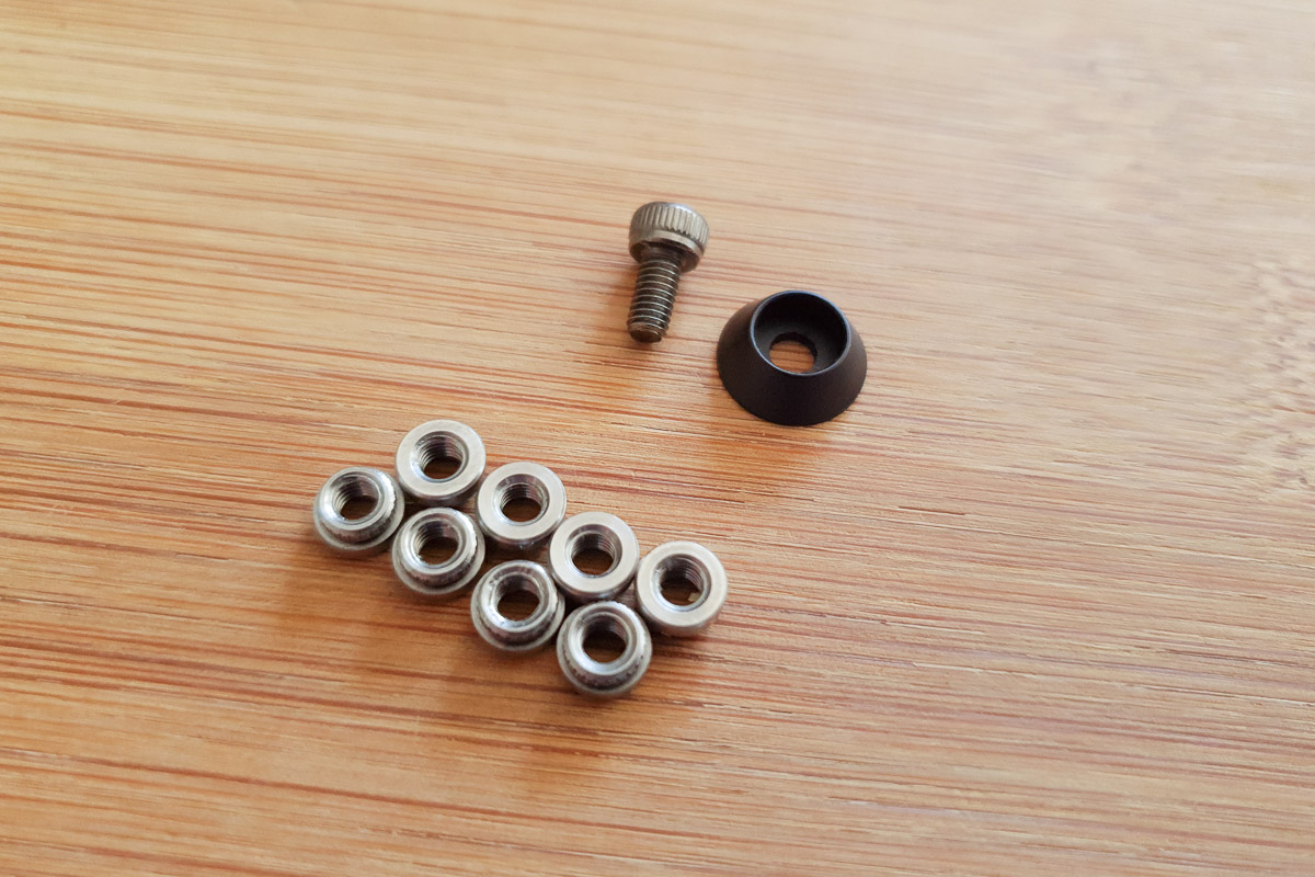
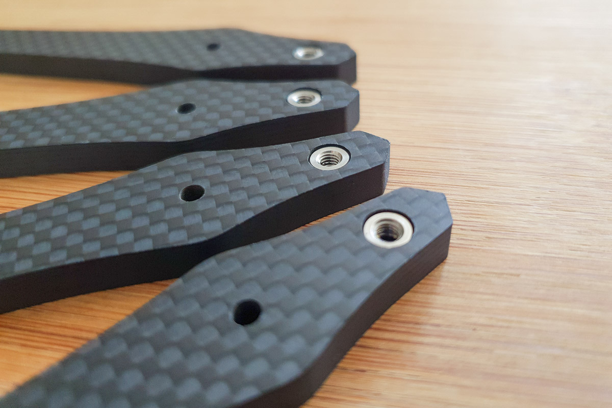
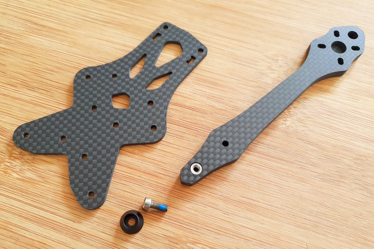
Step 2 - Arm Pressnuts
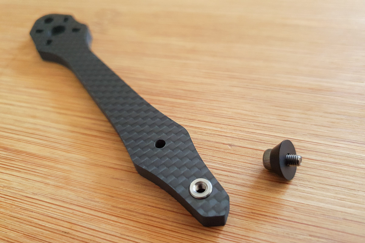
Install the pressnuts in to the four arms.
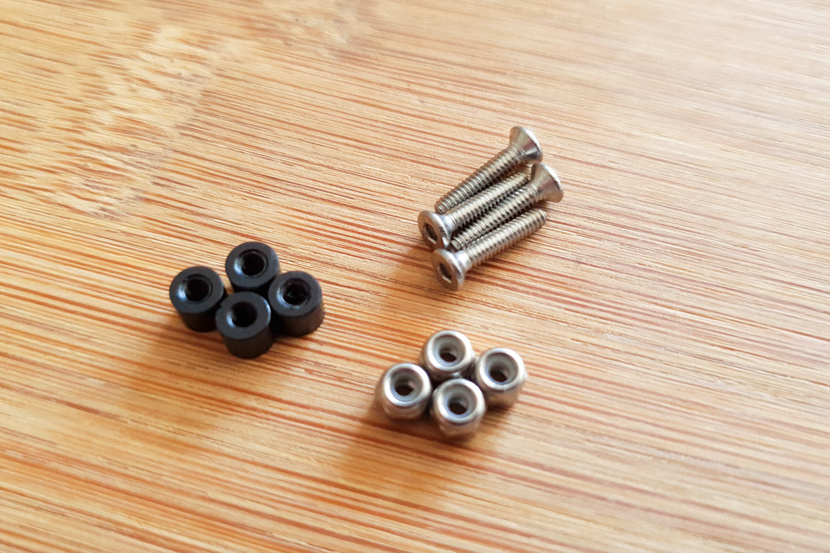
Prepare an M3x6mm cap head bolt and a cone washer.
Place a pressnut in to the hole at the end of the arm.
Pull the pressnut in to the arm from the oppsite side using the bolt and washer.
Repeat process for the remaining three arms.
Information
When fully installed the top of the pressnuts should sit just below the surface of the arm.
Warning
Pull the pressnuts in slowly and gently! Once you feel the shoulder of the pressnut reach the ridge inside the arm, stop immediately.
The pressnuts will become fully seated when securing the arms to the frame in Step 7.
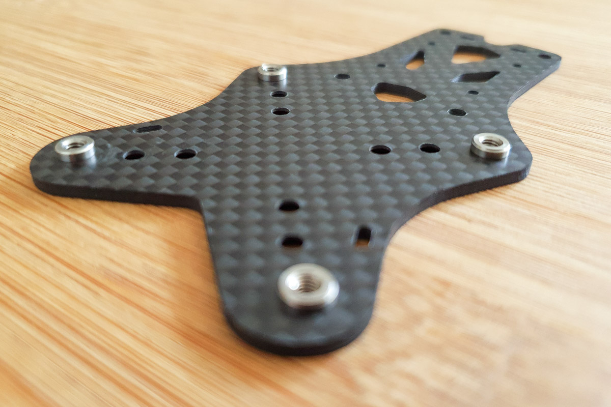
Step 3 - Upper Main Pressnuts
Install four pressnuts in to the Upper Main plate.
Prepare an M3x6mm cap head bolt and a cone washer.
Place a pressnut on one of the outer holes, on the opposite side of the plate to the countersinks.
Pull the pressnut in to the plate using the bolt and washer.
Repeat process for the remaining three pressnuts.
Information
When fully installed the shoulder of pressnut should sit flush with the plate.
Caution
Take care to install the pressnuts on the opposite side to the countersink holes.

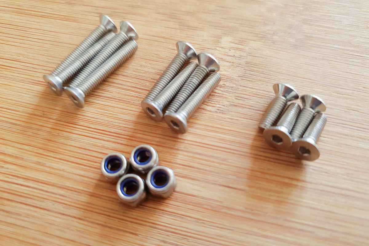
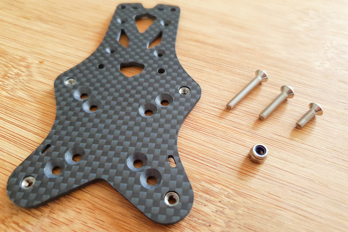
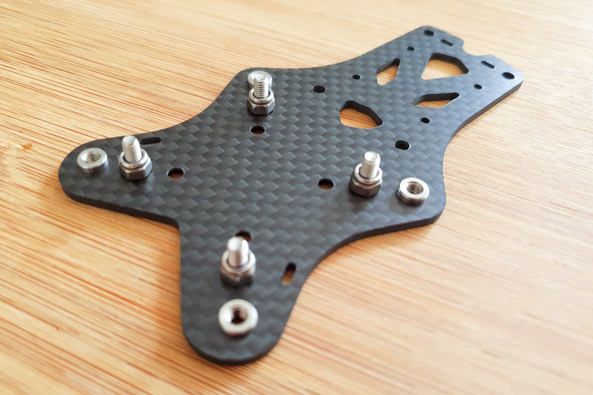
Step 4 - Stack Mounting Bolts
Install flight electronics stack mounting bolts.
Decide whether to use the 20x20 or 30x30 mounting holes.
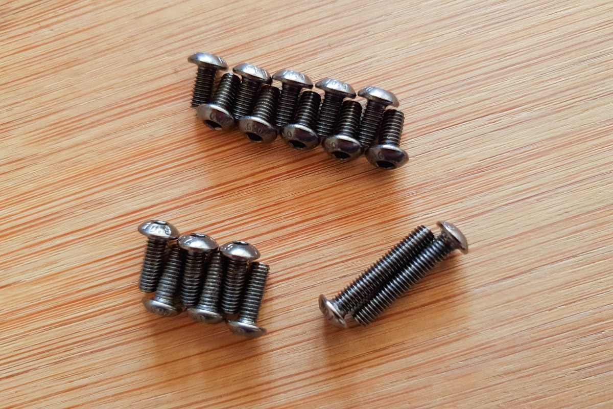
Decide whether to use the included M3 10mm, 16mm or 20mm countersink stack mounting bolts.
Place the bolts in to the selcted countersink holes and secure with an M3 nylock nut.
Tighten the nylock nut sufficiently such that the bolt will not rotate when installing additional mounting hardware to secure your stack.
Please consider which length of bolt will best suit the electronics you wish to mount.
Once the frame is assembled the heads of the stack mounting bolts are not directly accessible.
Information
The Mr Steele Light Weight kit comes with only one size of stack mounting bolts, M3x10mm in 7075-T6 aluminium, as well as aluminium nylock nuts.

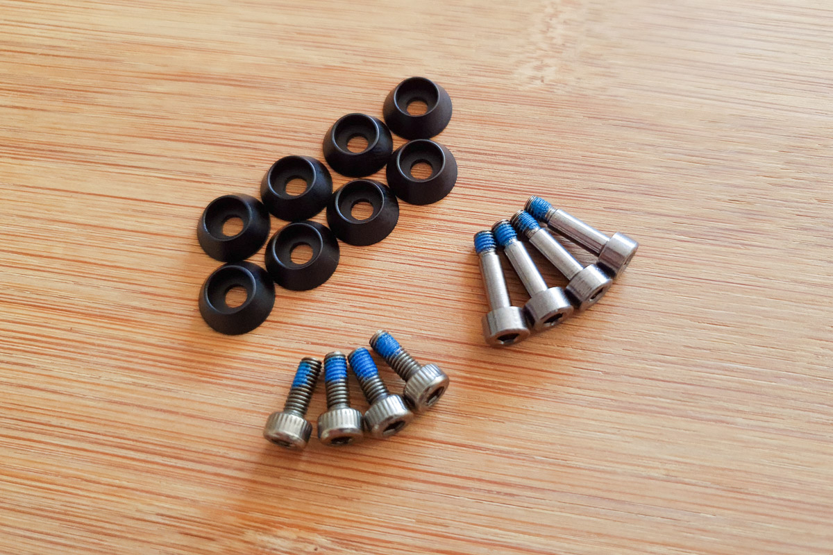
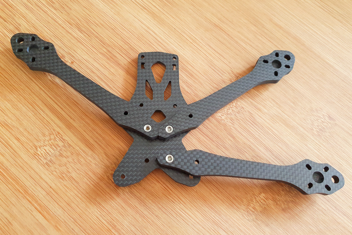
Step 5 - Arms and Key
Secure arms and key to lower main plate.
Prepare an M3x8mm cap head bolt with threadlocker and a cone washer.
Insert bolt with washer in to one of the inner arm mounting holes.
Attach arm to lower main plate using the embedded pressnut, do not fully tighten.
Repeat process to attach three arms.
-
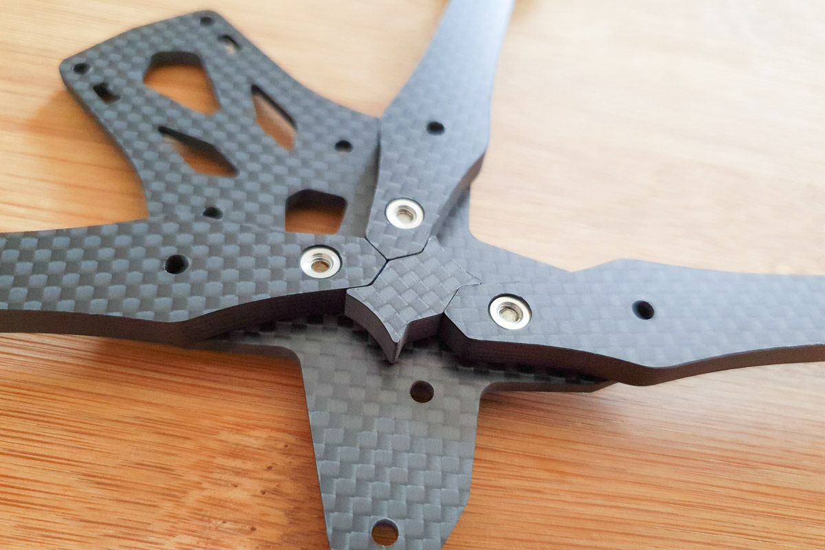
Rotate two arms such that they are correctly aligned and the tips are braced together. Rotate the third arm out to the side to create space to install the key.
Install the key and rotate the third arm in to position.
Attach the fourth arm to secure the key in place.
Information
Do not fully tighten the bolts, the arms should still be able to rotate.
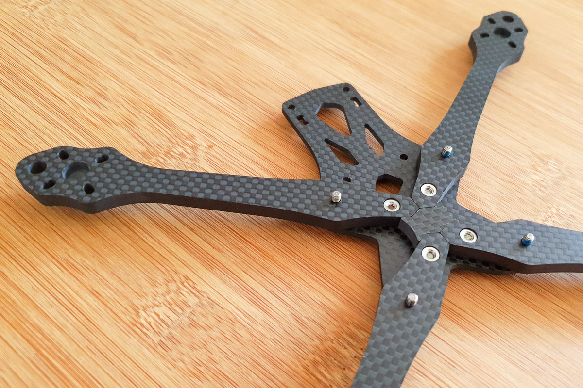
Step 6 - Shoulder Bolts
Install shoulder bolts through lower main plate and arms.
Prepare an M3 cap head shoulder bolt with threadlocker and a cone washer.
Insert bolt with washer in to one of the outer arm mounting holes.
Repeat process to install all four shoulder bolts.
The shoulder bolts should fit through the arms easily but without any lateral movement.
If one of the bolts begins to slide out when lifting the assembly, you can apply a light sideways force to that arm. This will create more friction to hold the bolt in place while you work.

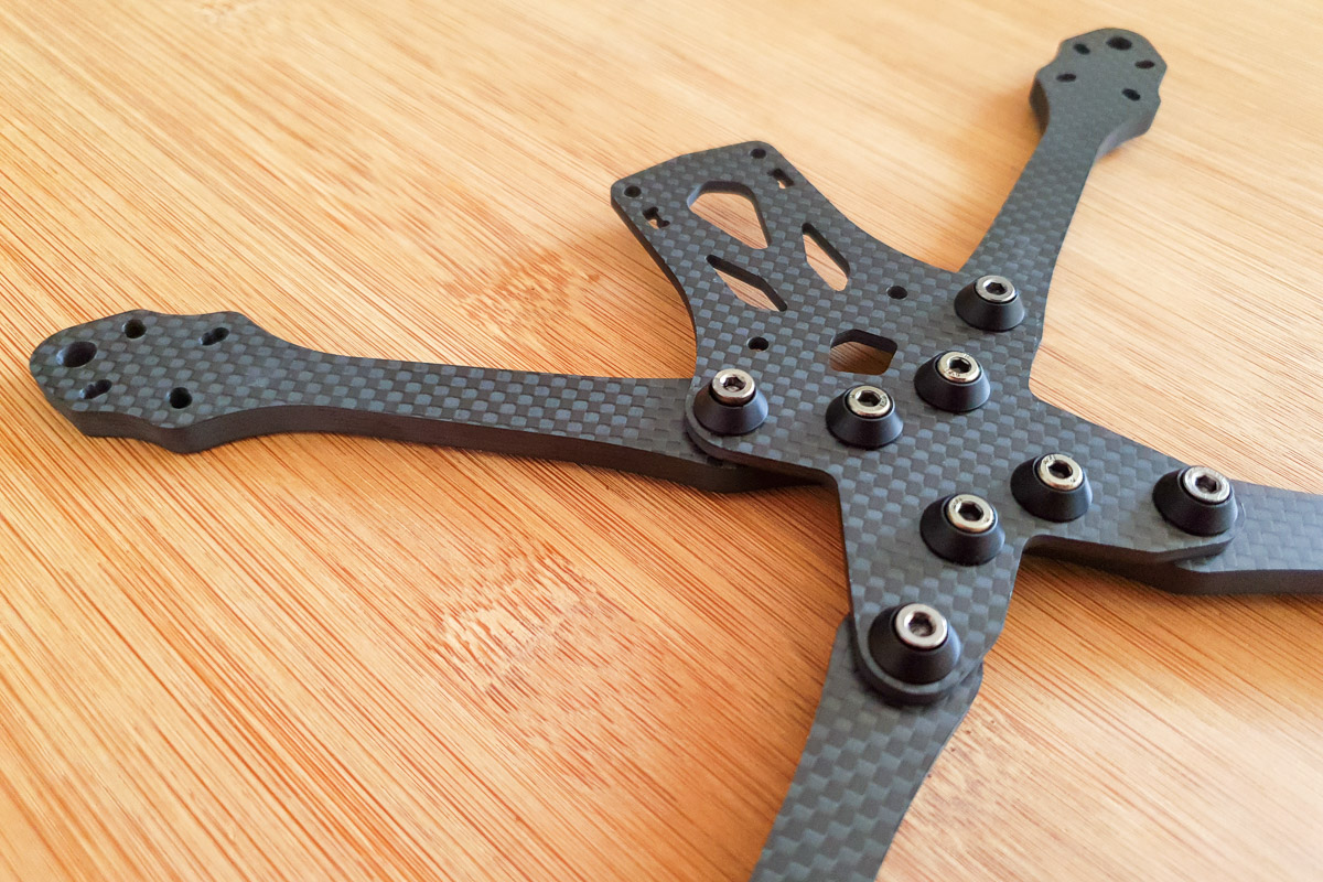
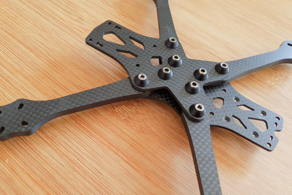
Step 7 - Upper Main
Install upper main plate.
Place upper main plate over the arms and align the pressnuts with the exposed threads of the shoulder bolts.
Tighten each of the shoulder bolts one revolution at a time, working in a star pattern, until fully secured.
Tighten the inner arm bolts installed in Step 5, working in a star pattern, until fully secured.
Information
Working from the outer bolts to the inner bolts and following a star pattern will ensure all components are correctly seated and aligned.

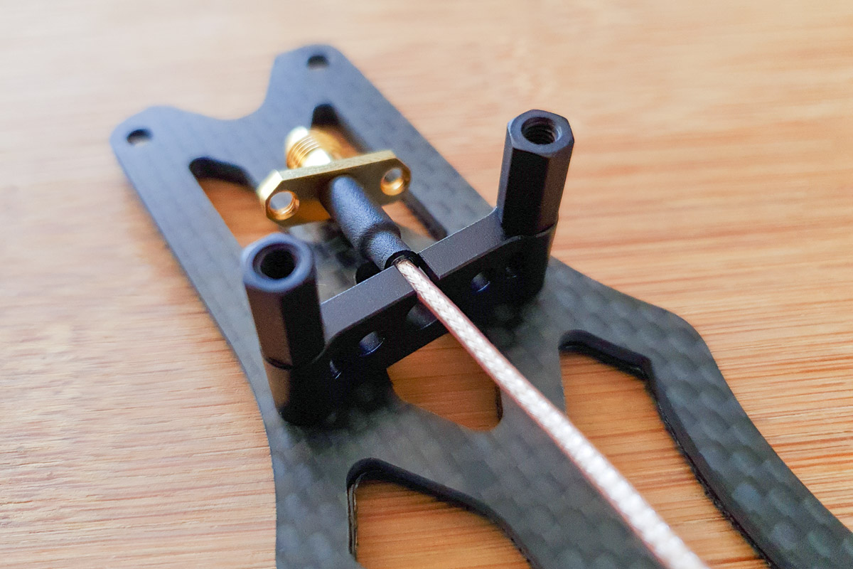
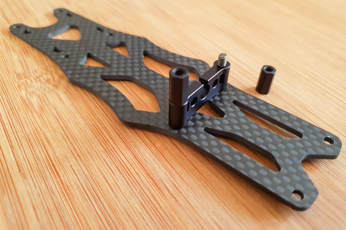
Step 8 - SMA Mount
Install SMA mount to top plate.
Place an M3x16mm button head bolt in to one of the rear three-quarter mounting holes.
Place SMA mount over the bolt and secure with a 10mm hex standoff.
Repeat process for the other side of SMA mount.
The SMA mount has slots on either side for a zip tie to secure your main battery leads.
This piece is optional and works best with a TBS SMA bulkhead mount as supplied with TBS Unify video transmitters. If you choose not to install this SMA mount we also include in the kit 20mm standoffs and M3x6mm button head bolts as replacements.
For TBS SMA bulkhead mounting instructions, please refer to the Antennas section of this page.
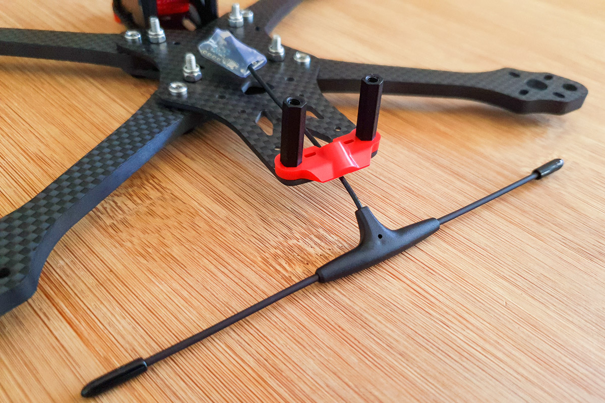
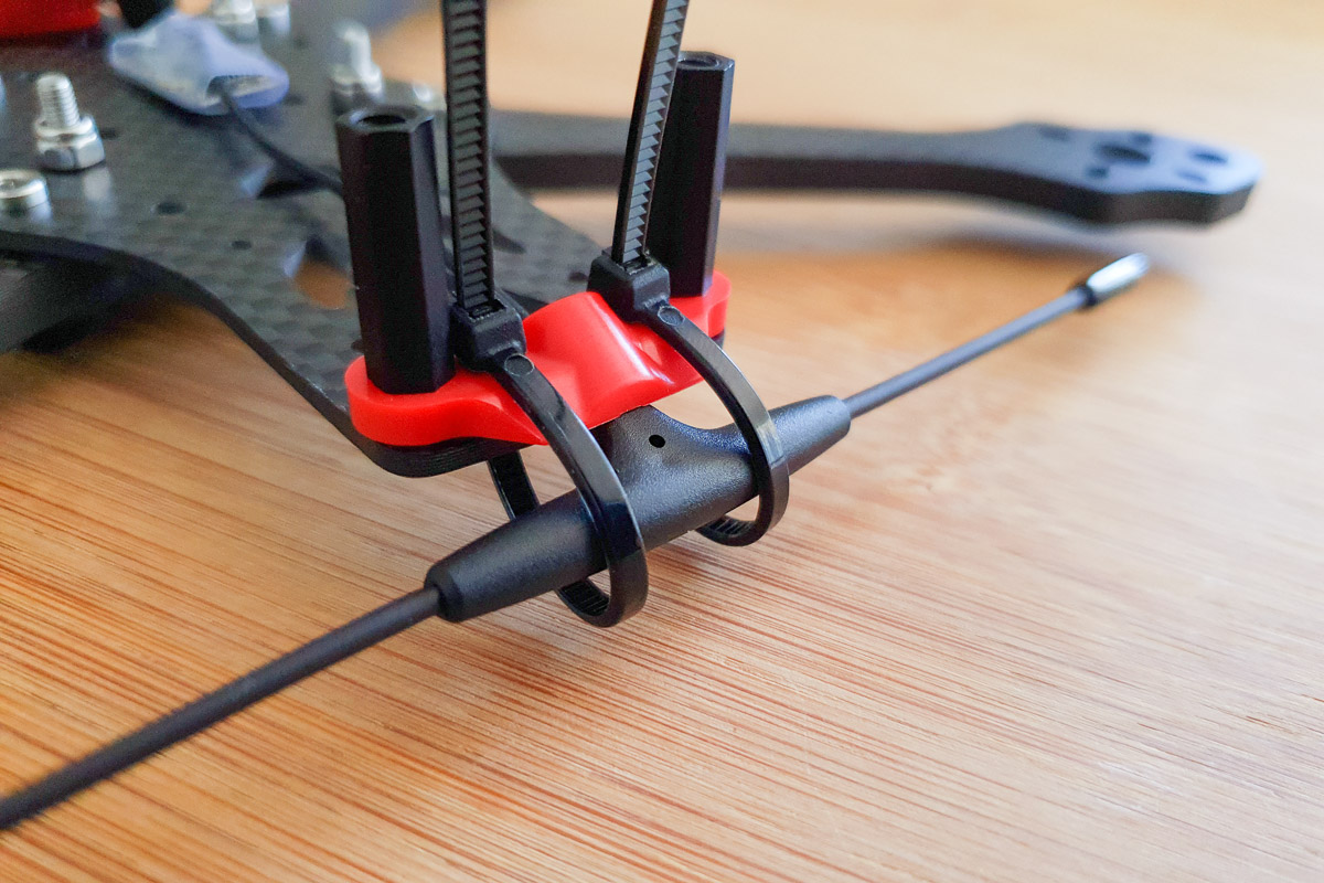
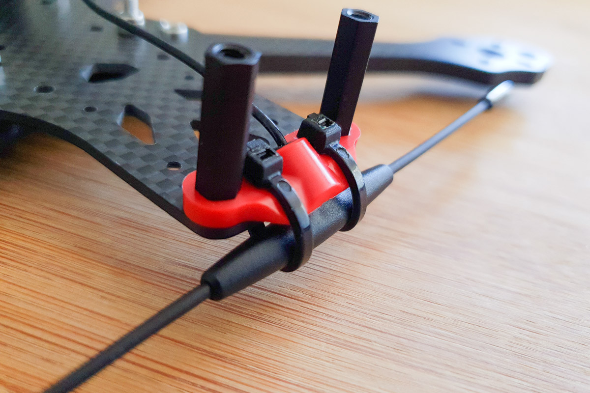
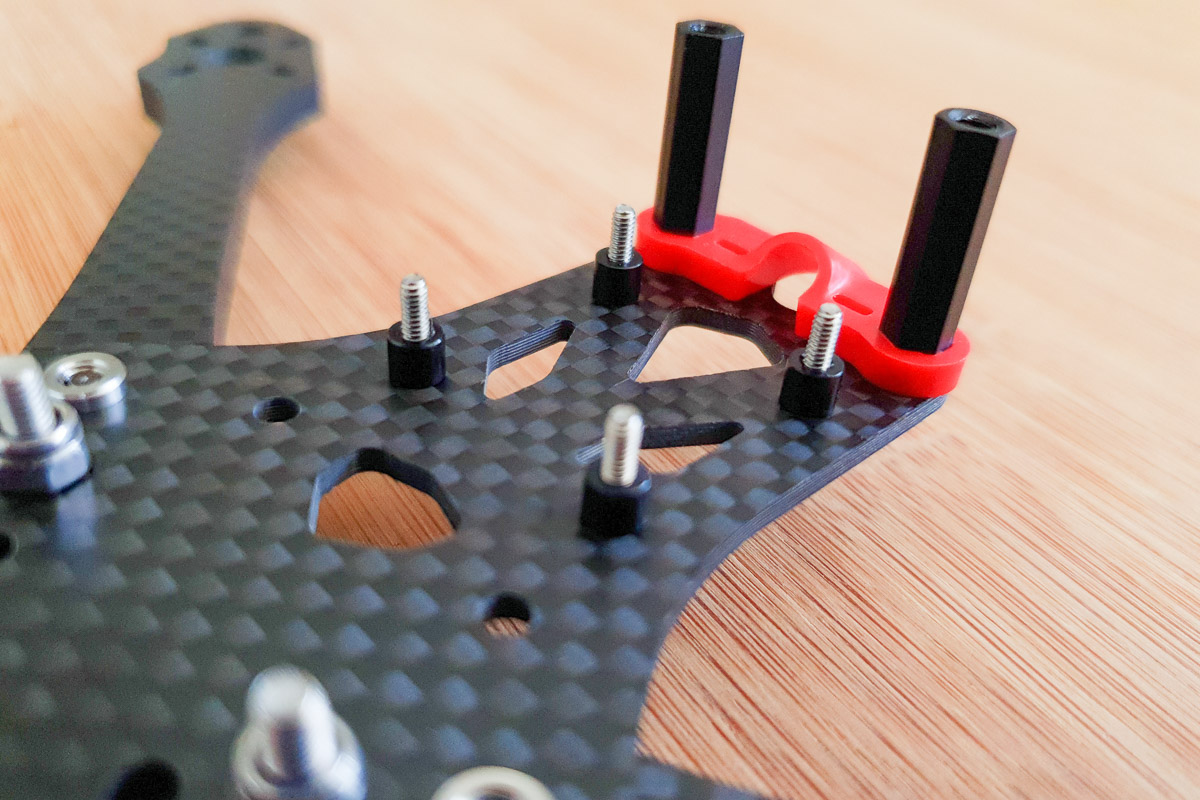
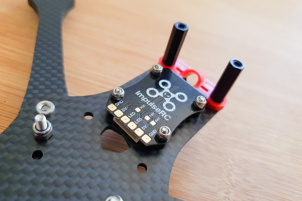
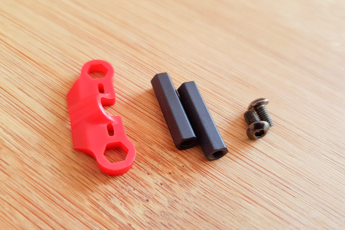
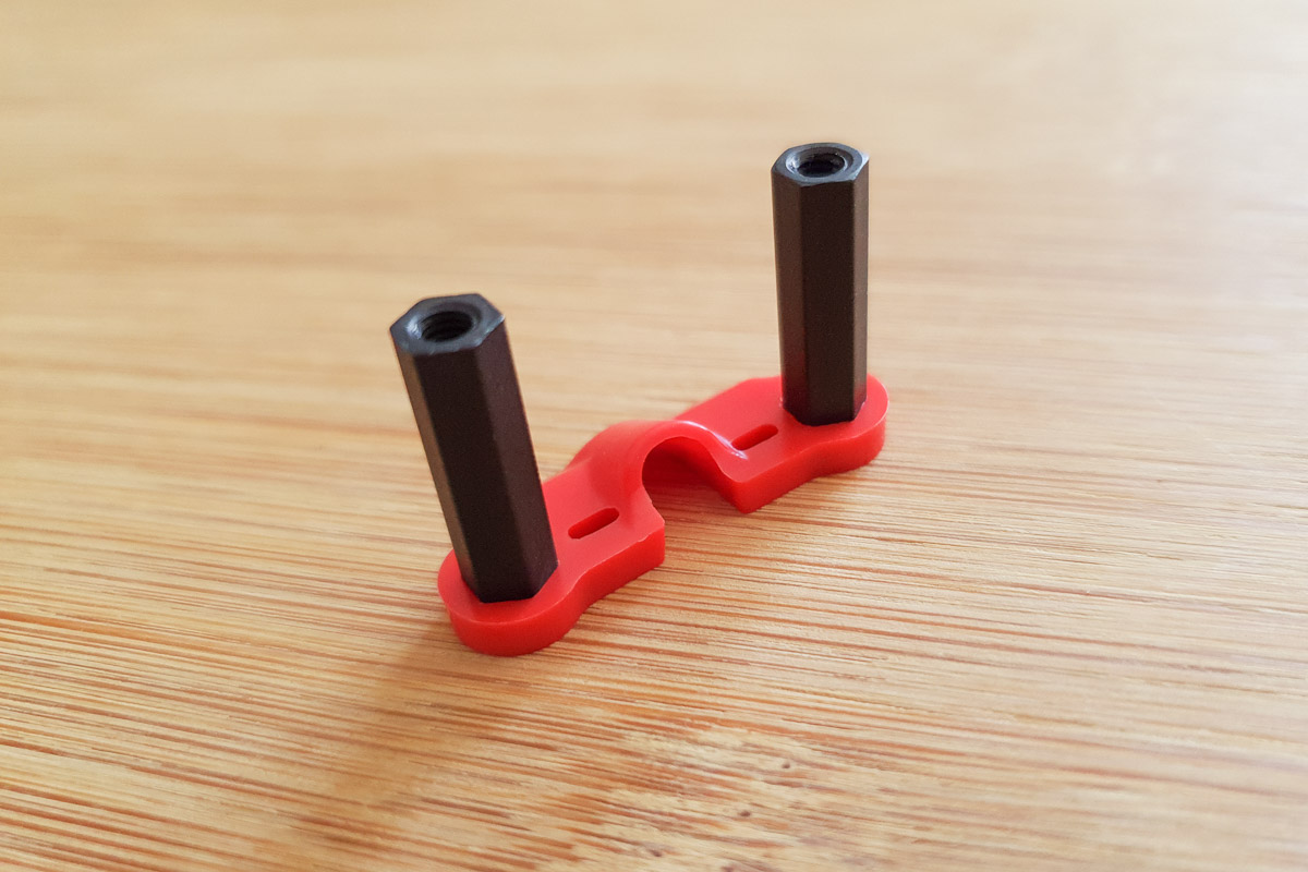
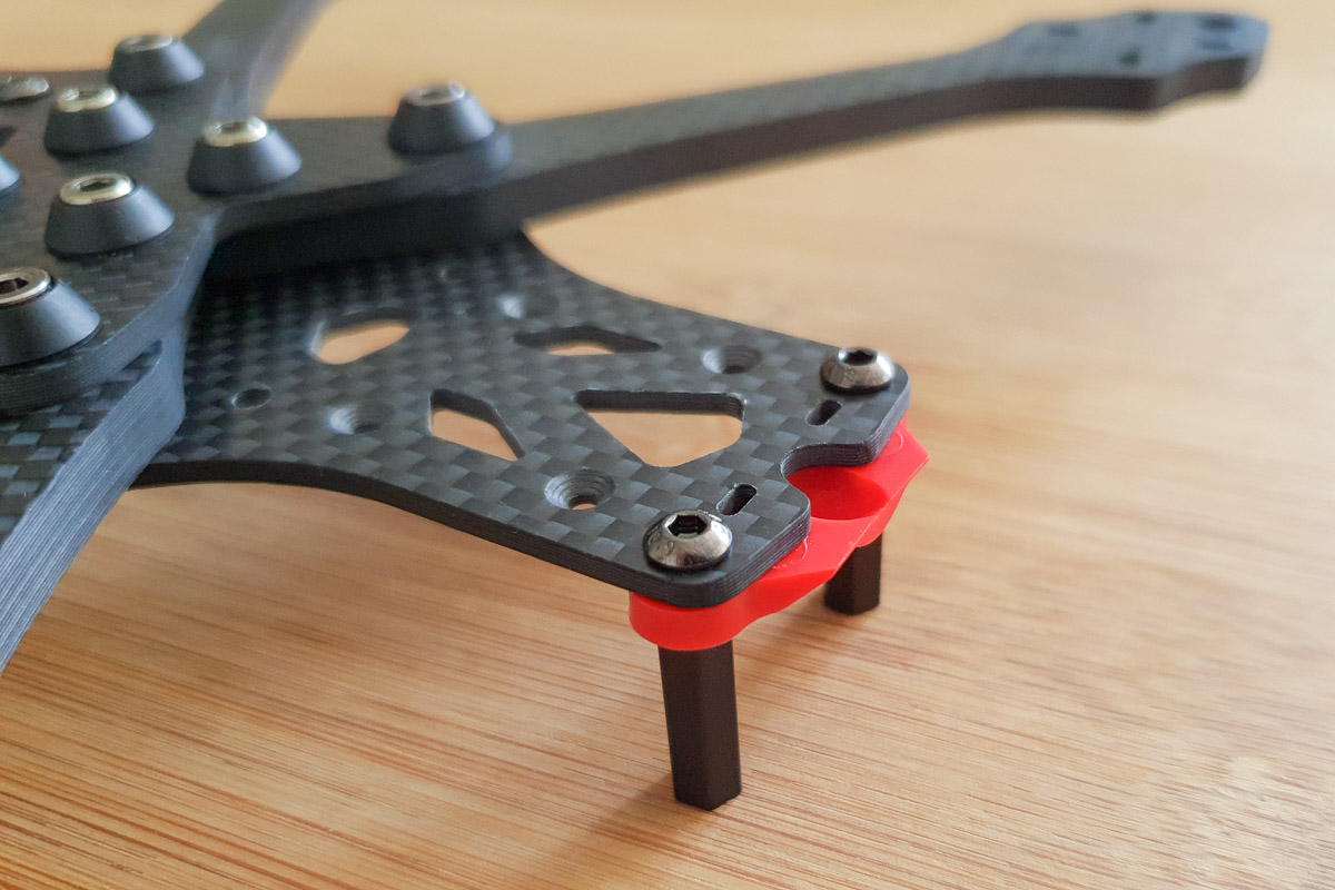
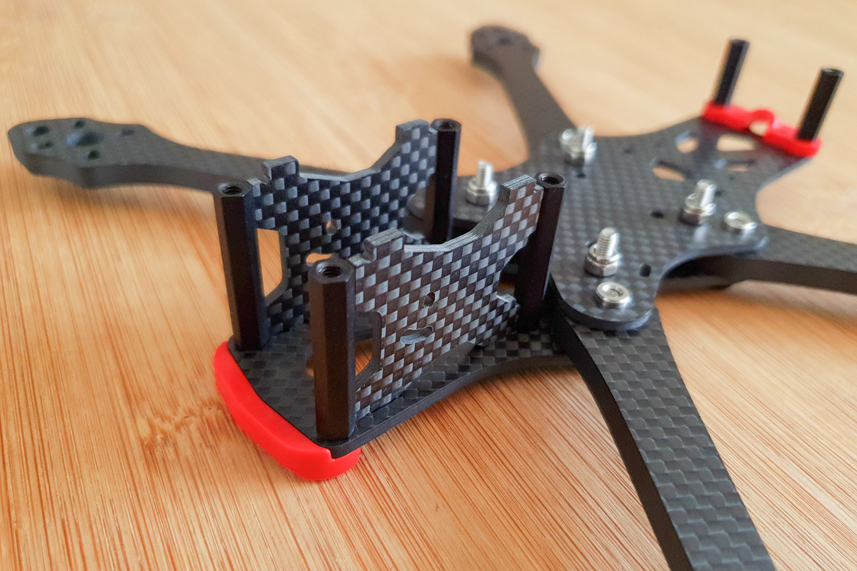
Step 9 - Immortal-T Clamp
Install Immortal-T clamp and rear standoffs to upper main plate.
Place two 20mm hex standoffs in to the Immortal-T clamp.
Secure the assembly to the upper main plate using two M3x6mm button head bolts.
This piece is optional, if you choose not to use an Immortal-T antenna or prefer another mounting method, simply install the standoffs to the upper main plate without the Immortal-T clamp in place.
For TBS Immortal-T mounting instructions, please refer to the Antennas section of this page.
Information
This part is not compatible with the HD Apex because the standoffs are spaced wider apart to fit the DJI Air Unit.
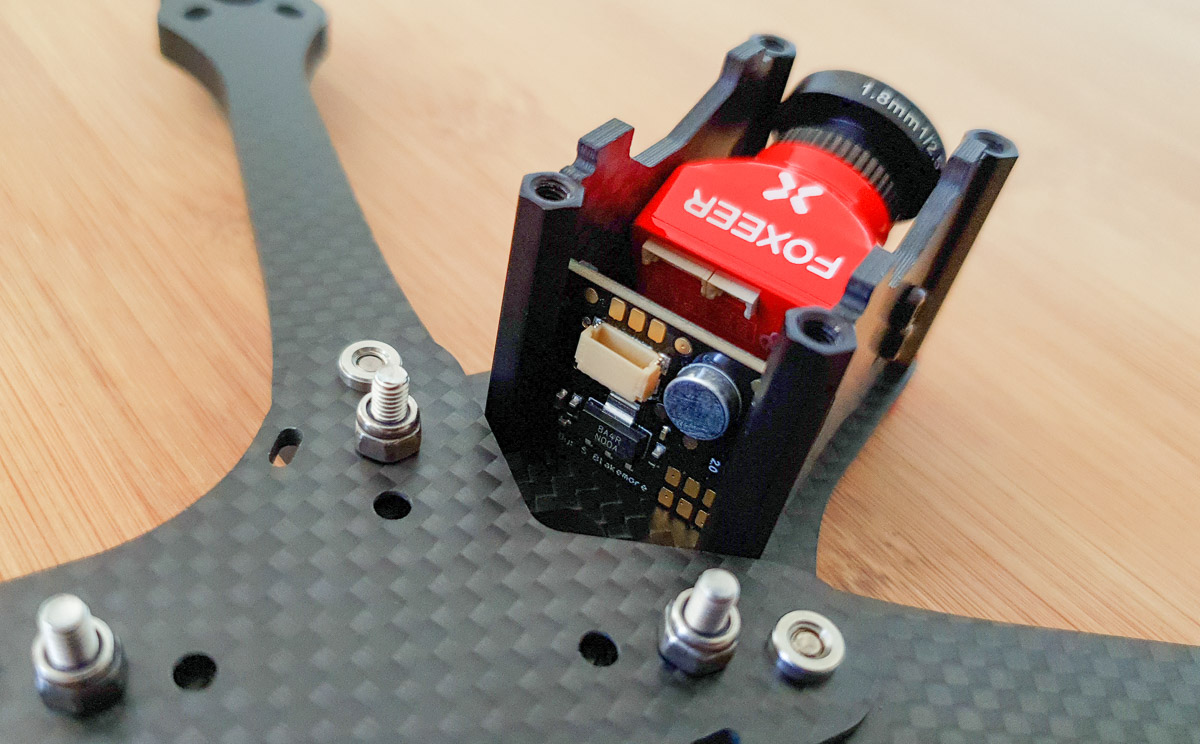
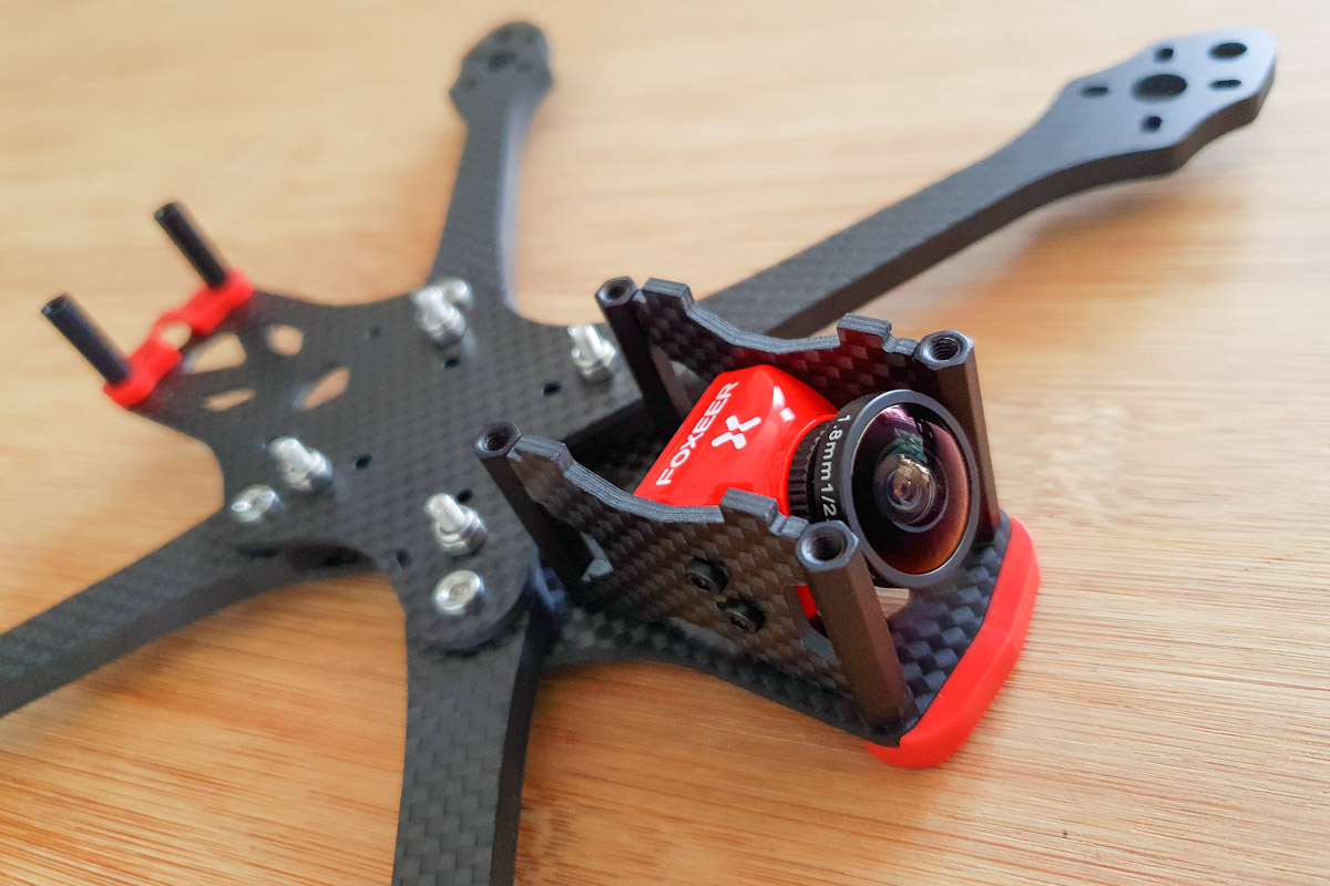
Step 10 - FPV Camera Mount
Install front bumper, camera plates and front standoffs to lower main plate.
Place an M3x8mm button head bolt through the front bumper and lower main plate.
Secure from above with a 28mm hex standoff, do not fully tighten.
Repeat for the other side of the front bumper.
Install the two further 28mm standoffs using M3x6mm button head bolts, do not fully tighten.
Align the four 28mm hex standoffs and install the camera side plates into the slots in the lower main plates.
Tighten all four bolts, taking care not to let the standoffs rotate out of alignment.
Install your FPV camera in to the frame using the M2x4mm bolts provided with the camera, do not fully tighten.
Information
The standoffs must be aligned such that one of the flat faces is braced against the edge of the camera plate. This bracing provides extra strength and structural integrity to the front of the frame.

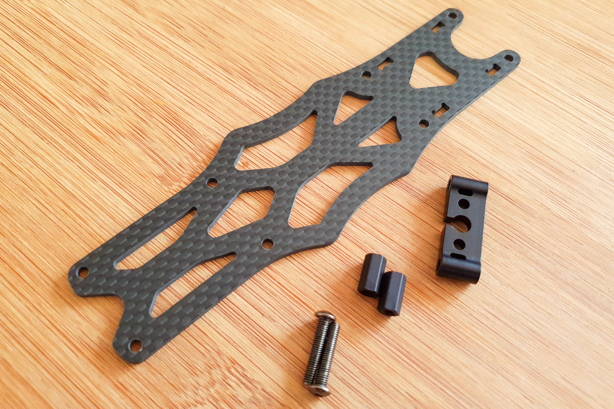
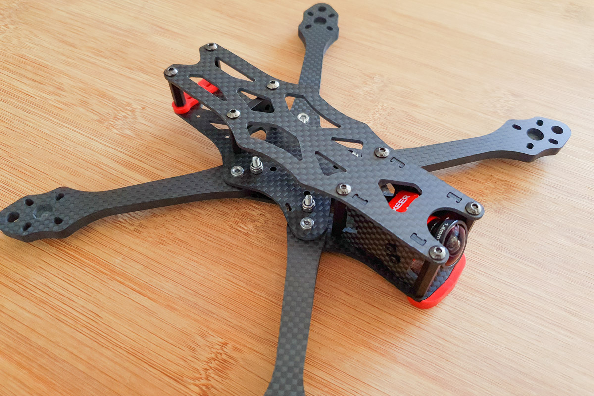
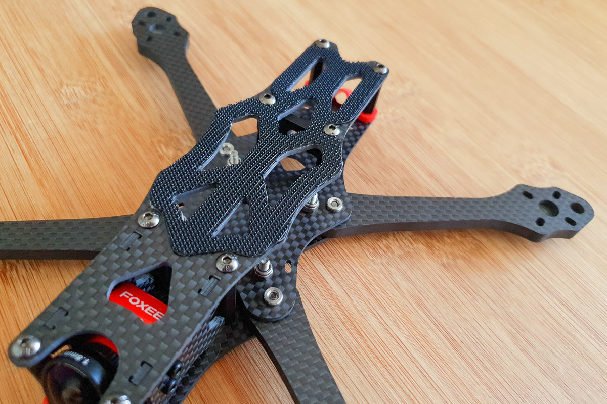
Step 11 - Top Plate
Install top plate and battery pad.
Place top plate over the frame and align the slots with the tabs on the camera plates.
Insert the tabs of the camera plates in to the slots of the top plate, adjusting the camera plate alignment as necessary.
Secure the top plate to the front four standoffs using four M3x8mm button head bolts.
Now the camera plates are held in place by the top plate, tighten the M2x4mm bolts holding the FPV camera.
Secure the top plate to the rear two standoffs using two M3x6mm button head bolts.
From below, secure the rear three-quarter standoffs to the upper main plate using two M3x6mm button head bolts.
Choose whether you would like to use the rubber or velcro battery pad and install on the top plate.
The front four button head bolts are 8mm long to support installing an HD camera mount.

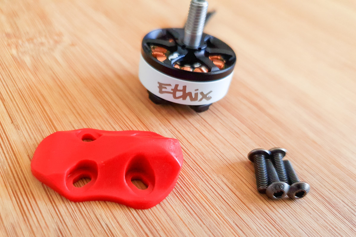
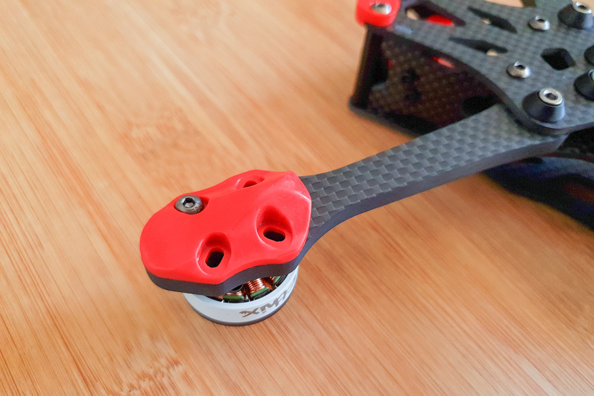
Step 12 - Motors
Install skids and motors to arms.
Place an M3x10mm button head bolt through a skid and arm from below.
Place a motor over the top of the arm and align mounting hole with exposed thread of the M3x10mm bolt.
Attach the motor to the arm with the M3x10mm bolt, do not fully tighten.
Repeat to install the further three motor bolts.
Tighten the four motor bolts in a star pattern.
Repeat with the remaining three skids and motors.
The skids and arms have both 16x16mm and 19x19mm mounting holes.
The motor skids are optional parts. We include both 8mm and 10mm button head bolts in the kit for securing the motors with or without the skids installed.
Information
The Mr Steele Light Weight kit comes with M3x8mm cap head bolts in 7075-T6 aluminium for mounting the motors without the skids. This is the preferred configuration of Mr Steele for the lightest possible build with a total weight saving of 25g over a build using steel hardware and skids.
We also include sixteen M3x10mm button head bolts in the Mr Steele Light Weight kit in case you do want to use the skids on your build.

Build Complete
Congratulations! You have completed the assembly of your Apex frame kit.
Now that the mechanical build is complete you can continue on to install your chosen flight electronics.